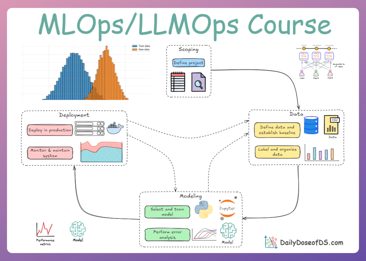
Model Deployment: Kubernetes
MLOps Part 12: An introduction to Kubernetes, plus a practical walkthrough of deploying a simple FastAPI inference service using Kubernetes.
Recap
Before getting into Part 12 of this crash course, let’s quickly recap what we covered in the last part.
In part 11, we began our discussion on the deployment and monitoring phase of the MLOps lifecycle.
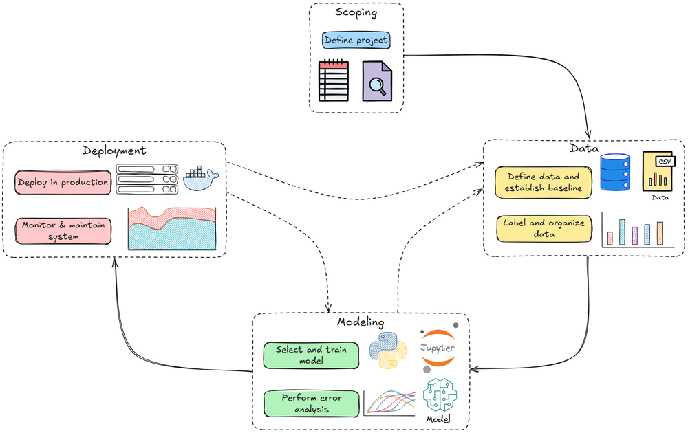
There, we learned about model deployment fundamentals, particularly model packaging formats, containerization, APIs, and the types of inference.
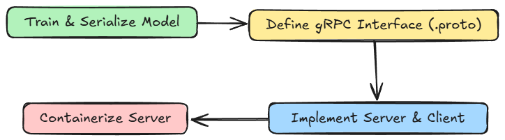
We also discussed gRPC in detail; the how and why, plus where it finds its suitable applications.

Finally, we walked through a comprehensive hands-on demo showing gRPC in action for ML settings.
If you haven’t explored Part 11 yet, we strongly recommend going through it first, since it sets the foundations and flow for what's about to come.
Read it here:
In this chapter, we’ll continue our discussion on the deployment phase, diving deeper into important concepts, specifically Kubernetes.
As always, every notion will be explained through clear examples and walkthroughs to develop a solid understanding.
Let’s begin!
Prerequisites
Before diving into Kubernetes, it’s essential to establish a foundational understanding of a few key concepts that underpin its architecture and philosophy. These include containerization, cloud-native principles, service meshes, immutable infrastructure, and microservices.
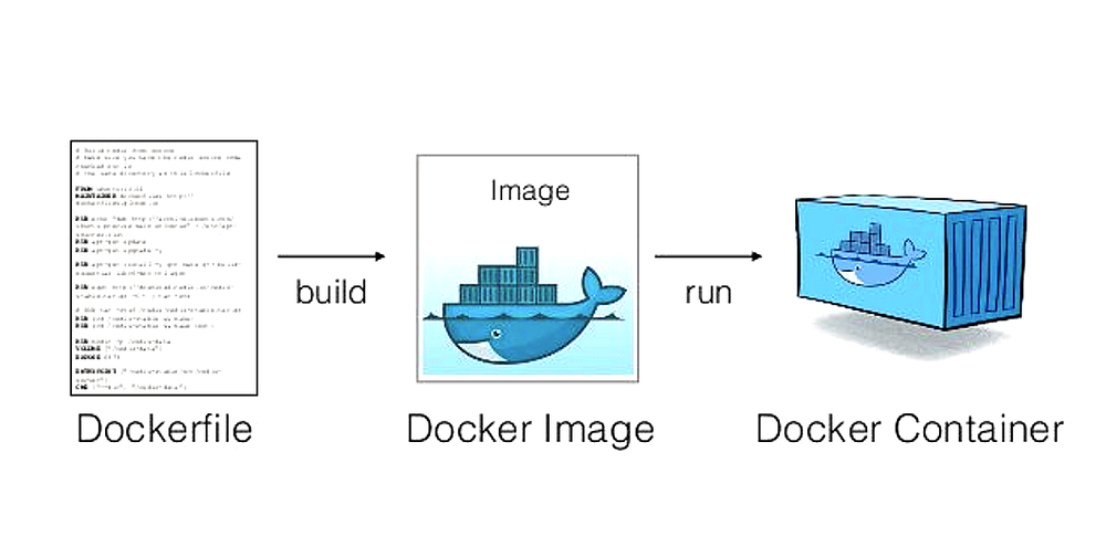
Images and containers basics
A container image is a lightweight, static, and immutable package containing all the necessary code, runtime, libraries, and configuration to run an application consistently across different environments.
A container, on the other hand, is a running, executable instance of a container image, functioning as a live application or service.
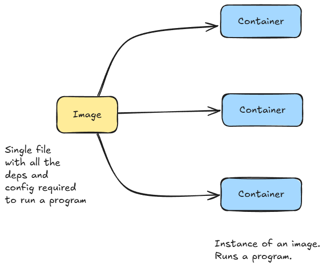
The image serves as a read-only template or blueprint, while the container is the active, isolated process that runs from that blueprint, similar to a class and its objects/instances in object-oriented design.
Because different applications often have conflicting dependencies, containers provide isolated environments, enabling multiple applications to run reliably on the same host without interference.
Cloud-native and microservices architecture
Cloud-native refers to designing and building applications specifically for the cloud environment, emphasizing scalability, resilience, and agility through modern development practices and cloud infrastructure.
The cloud-native ecosystem is typically composed of:
- Containers: lightweight, portable execution units
- Service meshes: managing service-to-service communication
- Microservices: modular application components
- Immutable infrastructure: ensuring reproducibility and consistency
- APIs: enabling interoperability and integration
Together, these components form the backbone of scalable systems that can be continuously deployed and updated with minimal downtime.
Service meshes
A service mesh is an infrastructure layer that manages and secures communication between microservices.
It provides features such as:
- Traffic management and load balancing
- Encryption and service authentication
- Observability through metrics, logging, and tracing
By offloading these concerns to the mesh (via proxy sidecars attached to each service), developers can focus on writing business logic, while operations teams manage reliability and performance uniformly across the system.
Immutable infrastructure
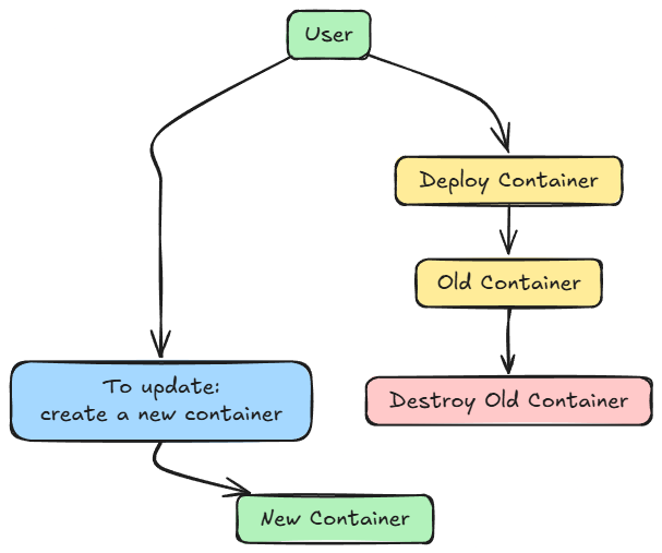
Immutable infrastructure is the practice of never modifying a deployed component, such as a server or container, after it’s running.
When an update or configuration change is required:
- A new version of the system is built from a standardized image.
- It’s then deployed to replace the existing instance.
- The old instance is decommissioned once validation (e.g., A/B testing or canary deployment) confirms success.
This approach guarantees consistency, reliability, and reproducibility, as every deployment begins from a clean, known state.
A prime example is Docker containers, where each change means the creation of a fresh container.
Containers epitomize immutability; they are ephemeral and disposable, often described as “cattle, not pets”, highlighting a shift from manual maintenance to automated, scalable management.
Microservices
This is a variant of Service-Oriented Architecture (SOA) that arranges an application as a collection of loosely coupled, fine-grained services.
Each service represents a specific functionality, providing a well-defined interface for other applications to consume without needing to know the internal implementation.
Some key points about microservices:
- Services communicate using lightweight protocols (e.g., HTTP or gRPC).
- They can be scaled independently and built by smaller teams using different programming languages.
This modular approach fosters agility, enabling faster development, deployment, and maintenance cycles.
With these foundational concepts in place, we now have the essential groundwork for understanding how Kubernetes orchestrates and manages applications.
Kubernetes: introduction
Kubernetes is an open-source system for automating the deployment, scaling, and management of containerized applications. It simplifies complex applications by orchestrating containers (packaged, portable units of software).
Why Kubernetes?
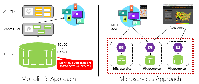
Over the last decade, many software systems (including ML systems) migrated from monoliths to microservices / modular architectures. Each component (e.g., model-serving, data ingestion, API front end) is packaged in containers.
A microservices (or modular) architecture, on the other hand, breaks this big system into smaller, independent components, like separate “mini-apps” where each responsible for one function (for example, data ingestion, model serving, or the API). These smaller parts communicate with each other, often through APIs, and can be developed, deployed, and scaled independently.
However, when you have many containers across many machines (or nodes), managing them manually becomes hard:
- Which node should run which container?
- How to recover automatically, in case of failure?
- How to scale containers up/down with load?
- How to route traffic among them?
- How to do rolling updates (updates with zero downtime)?
Kubernetes, as a container orchestration system, automates much of that complexity.
What Kubernetes provides?
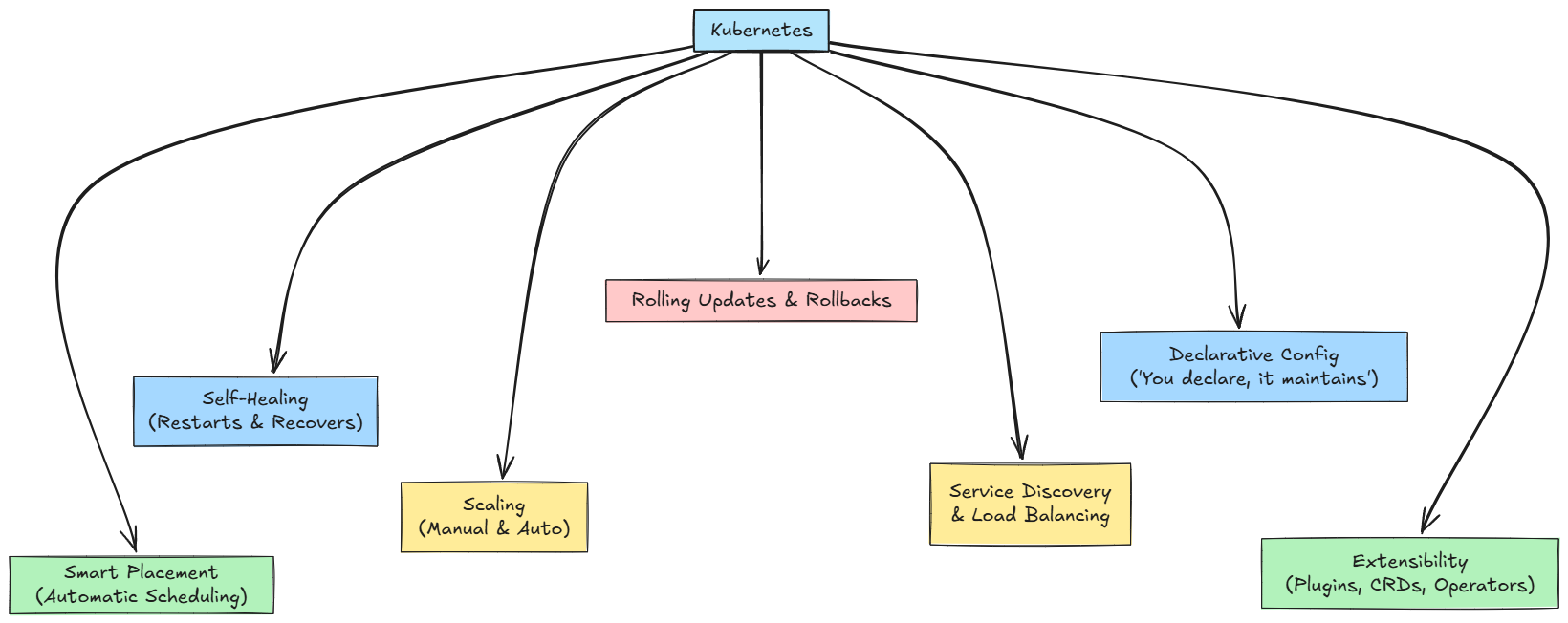
Some of the key features of Kubernetes are:
- Automatic scheduling: Kubernetes decides on which node(s) to place containers (or pods, as the primitive) based on resource requirements and policies.
- Self-healing: If a container crashes, Kubernetes restarts it. If a node dies, it shifts the container to a healthy node.
- Scaling: It supports both manual and auto-scaling (based on CPU, memory, and custom metrics).
- Rolling updates & rollbacks: You can update container versions with minimal downtime, and rollback if something fails.
- Service discovery & load balancing: Containers can find each other via DNS, internal IPs, and requests are balanced among replicas.
- Declarative configuration: You specify what the cluster should look like (e.g. “3 instances of model-serving”), and Kubernetes works to maintain that state.
- Extensibility & ecosystem: Many add-ons, custom resource definitions (CRDs), operators, service meshes, etc.
Here's a quick summary diagram of the above-described features:
Kubernetes helps you deploy and manage model-serving, scalable inference endpoints, and microservices reliably in production.
With this introduction to Kubernetes in mind, let’s explore some of the architectural and conceptual details of Kubernetes.
Kubernetes: high-level architecture & core concepts
Cluster, control plane & worker nodes
At its core, a Kubernetes system is a cluster, composed of:
- One (or more) control plane(s) (also called master nodes) that are responsible for making global decisions, scheduling, and maintaining cluster state.
- Several worker nodes: the machines that actually run workloads (containers) under instructions from the control plane.
The control plane and nodes communicate over APIs and internal protocols.
You can think of it like this:
- Control plane = "brain/decision maker"
- Worker nodes = "execution agents/workers"
Each cluster must have at least one worker node to run workloads; control plane components can themselves run on separate machines or co-locate (in simple setups).
The cluster architecture diagram below shows:
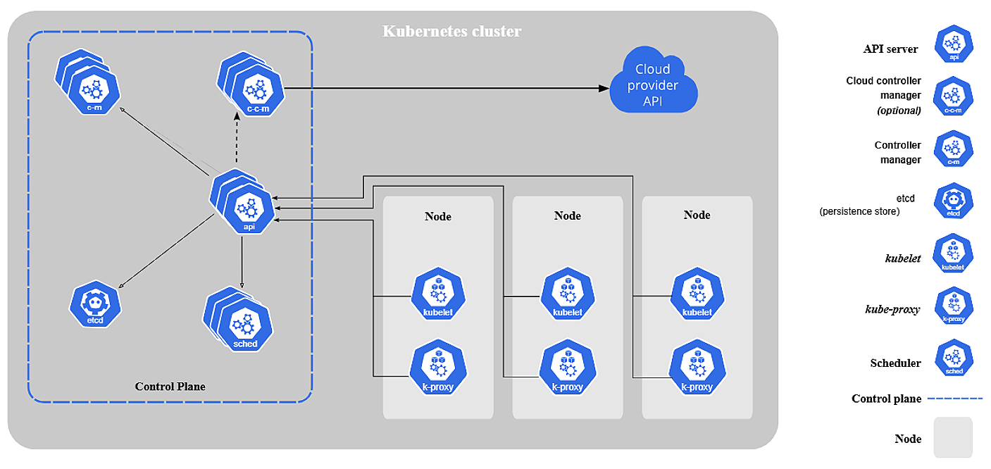
- Control plane components:
kube-apiserver,etcd,kube-scheduler,controller manager - Worker node components:
kubelet,kube-proxy, container runtime, pods & containers - The networking layer connecting all nodes, and external access via
Service,Ingress, etc.
Basic terminology/abstractions
Before diving deeper, we must understand a few key terms:
- Pod: The smallest deployable unit in Kubernetes. A pod can host one or multiple tightly coupled containers, which share the same network namespace (IP).
- Node: A physical or virtual machine in the cluster, running pods.
- Cluster: A set of nodes managed by a control plane.
- Namespace: A logical partitioning inside a cluster (to isolate resources).
- Deployment and ReplicaSet: Higher-level abstractions (workloads) to manage pods, specify how many replicas, etc.
- Service: A stable abstraction (IP + DNS) over pods to allow reliable access (load balancing, discovery).
- Ingress/Ingress Controller: Manages external access (HTTP routing) into services.
- ConfigMap/Secret: For passing configuration or sensitive data into pods.
- Volume/PersistentVolume: Storage abstractions for mounting data into pods.
- Label & Selector: Key-value tags attached to objects, used to filter / group resources (e.g. choose which pods a service should route to).
- API objects: Kubernetes resources are represented as API objects with
spec(desired state) andstatus(current state).
These abstractions allow you to think declaratively: define what you want, not step-by-step how to manage containers.
Now, let’s dive into the controlling logic.
Control plane components
These components coordinate the cluster-wide behavior, enforce the desired state, schedule workloads, etc.

kube-apiserver (API Server)
- This is the front door for the Kubernetes control plane. It exposes the Kubernetes API (RESTful), accepting HTTP/HTTPS requests (
kubectl, controllers, other components) for CRUD operations on Kubernetes resources (Pods, Deployments, Services, etc.). - All components communicate via the API Server (i.e., controllers, scheduler, nodes).
- The API server also interacts with the persistent store (
etcd) to read/write cluster state. - It performs validation, authentication & authorization.
In short, it is the central hub. Without the API server, nothing else functions.
etcd (key-value store)
etcdis a distributed, strongly consistent key-value store that holds the entire cluster state (all Kubernetes object definitions, configurations, resource statuses, etc.).- It is the source of truth: every change to cluster resources is persisted here.
- Kubernetes control plane components watch
etcdfor changes and respond appropriately.
Because etcd is critical, you typically run it redundantly (multiple replicas) in production to avoid a single point of failure.
kube-scheduler
- The scheduler’s job is to pick which node a newly created pod should run on.
- It watches for unscheduled pods (i.e., pods without a node assignment) via the API server, then applies scheduling logic: resource constraints (CPU, memory), tolerations, node capacity, etc.
- Once it picks a node, it binds the pod to that node (via the API server).
kube-controller-manager (Controller Manager)
Runs a set of controllers as separate control loops (in a single binary). Controllers monitor the cluster state and make changes until the desired state matches the actual state.
Examples include:
- Replication controller/ReplicaSet controller: ensures the specified number of pod replicas are running.
- Deployment controller: handles rolling updates, rollbacks, and scaling changes.
- Node controller: monitors node health and reacts (e.g., mark node as “Not Ready”).
- Service controller: handles service/endpoint objects.
- Namespace controller, Garbage collector, etc.
Each controller loops constantly: read state, then compare to the desired state, and finally take action to reconcile.
Together, these components maintain global cluster behavior: scheduling, scaling, reacting to failures, and maintaining consistency.
Node/worker components
These are the components on each worker node that carry out the execution of pods, manage networking, report status, etc.
kubelet
- The
kubeletis an agent that runs on every node. - It watches the API server for assigned pods, and ensures containers in those pods are running and healthy (via container runtime).
- It starts/stops containers, reports status, handles health probes (liveness/readiness), etc.
- It also sends heartbeats/status updates to the control plane.
In short, the control plane tells kubelet “run these pods”, and the kubelet ensures they are running correctly on that node.
Container runtime (CR)
- On each node, you need a container runtime that can actually pull container images, create and manage containers per spec.
- Kubernetes interacts with it via the Container Runtime Interface (CRI).
- Kubernetes historically used Docker as the container runtime, but now has evolved to support runtimes like Containerd.
kube-proxy (network proxy)
kube-proxyruns on each node and helps implement Kubernetes Service abstraction (cluster IP, load balancing).- It watches the API server for Service and Endpoint changes, and then configures local rules (iptables, IPVS) to forward traffic as needed to the actual pods backing a service.
- It ensures that when a request hits a service’s virtual IP, traffic is forwarded to healthy pods.
Hence, each node participates actively in running containers and networking while reporting back to the control plane.
Now that we understand all the different components, let's go ahead and see how they all actually interact together.
How components interact: workflows and control loops
Understanding the interaction patterns provides insight into how declarative behavior emerges. Let's explore the mechanisms in detail to see exactly how things work:
Desired state → actual state → reconciliation
- The user or system submits an API object (e.g. a Deployment job specifying 3 replicas, container image, resource limits).
- This goes to the API server, gets stored in
etcd. - The relevant controller (Deployment controller, ReplicaSet controller) sees that the current state (zero replicas) does not match the desired state (3), so it creates 3 pods.
- For each pod, the scheduler assigns a node.
- The API server communicates with that node’s kubelet.
- The kubelet (on that node) pulls the container image and starts containers via the container runtime.
- The node reports back its status.
- The controller keeps checking, and if a pod fails, it restarts or recreates until 3 are healthy.
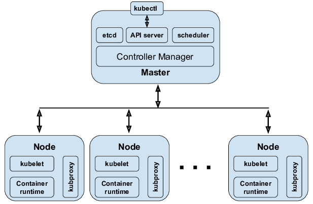
Here is the high-level flow of desired state maintenance as a diagram:
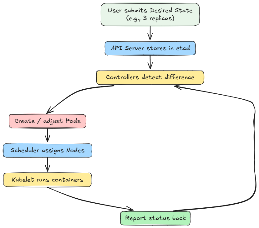
This is the control loop/reconciliation model: it continuously converges towards the declared desired state.
Service discovery & routing
- A Service object defines a logical set of pods (via label selectors) and an abstract IP + port.
kube-proxysets up rules so any traffic coming to thatIP:portis forwarded to one of the pods backing it (load-balanced).- Pods refer to services via DNS (CoreDNS), so they can discover each other stably, without knowing dynamic pod IPs.
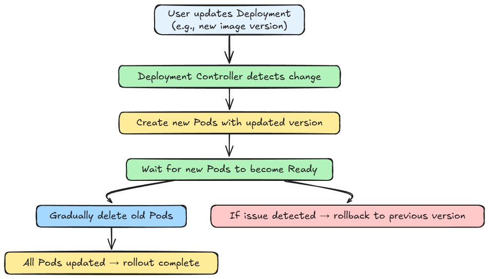
Rolling updates
- When the user updates a Deployment (change container image version), the Deployment controller (classic rollout logic) gradually replaces existing pod replicas with new version pods (e.g., create new pods, wait for readiness, delete old ones).
- If something goes wrong, rollbacks can be triggered.
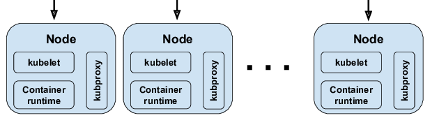
Here is the complete flow summarized as a diagram:
Failure handling
- If a node fails/becomes unreachable, the Node controller marks it as “NotReady.”
- Pods on that node are eventually considered lost, and replacement pods are scheduled on healthy nodes.
- If a pod container crashes or fails a readiness probe, the kubelet restarts it (if defined to).
- Controllers monitor and enforce replica counts, so the system remains resilient.
Autoscaling
- Horizontal Pod Autoscaler (HPA): monitors metrics (CPU/memory/custom metrics) and scales the number of replicas.
- Vertical Pod Autoscaler (VPA): adjusts the CPU and memory requests and limits for containers within pods to "right-size" them based on historical resource usage.
- Cluster autoscaler (in cloud setups): adds or removes nodes based on demand so that pods can be scheduled.
Thus, the system can automatically adapt to load and failure.
Now that we understand the different core components and how they work and interact with each other, let's go ahead and dive into a practical exercise on Kubernetes.
Hands-on: Kubernetes in action
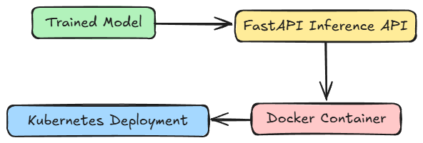
In the previous part, we had trained a basic regression model that mapped the relation $y=2x$. We'll use the same model file, and we will:
- Create a simple inference API using FastAPI
- Containerize the API using Docker
- Deploy the containerized application using Kubernetes
Project setup
The code and project setup we are using are attached below as a zip file. You can simply extract it and run uv sync command to get going. It is recommended to follow the instructions in the README file to get started.
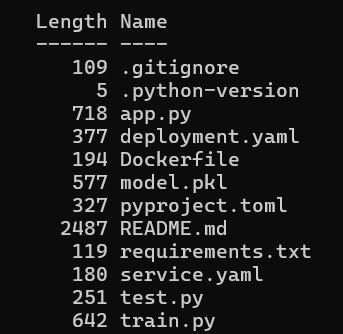
Download the zip file below: